![]()
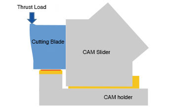
Thrust load transferred from trimming gets offset within the cam unit.
•Capable to withstand thrust load from all directions, right and left, up and down.
•Thrust pad no longer needed in the die.
•Space saving
Horizontal thrust to be supported perbendicular to the surfaces minimizing snifting, which results in minimizing burrs.
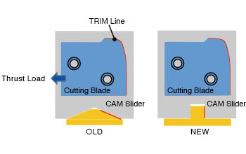
Supporting surface made in the cam holder for the cutting blade, which is designed to minimize mis-aligument at the processing areas.
Please click the link below to see cam detail.
| Grade |
Cam width [mm] |
Working Force[kN(tonf)] |
Angle (10-degree increment) |
Catalog No. |
Spring Type | Application | ||
|
1,000,000 strokes |
1,000,000 strokes with conditions |
300,000 strokes with conditions |
||||||
| ● | 100 |
57.8 (5.9) |
86.7 (8.8) |
103.9 (10.6) |
0°~70° | VACYHT100 |
|
Trim Flange |
| 140 |
90.2 (9.2) |
112.8 (11.5) |
135.3 (13.8) |
0°~70° | VACYHT140 |
|
||
| ● | 100 |
57.8 (5.9) |
86.7 (8.8) |
103.9 (10.6) |
0°~70° | VACPHT100 |
|
Trim Flange |
| 140 |
90.2 (9.2) |
112.8 (11.5) |
135.3 (13.8) |
0°~70° | VACPHT140 |
|
||
Copyright © 2020 Sankyo Oilless Industry, Inc. All Rights Reserved.